Four ways your VFD can ruin your motor
As a working professional with a background in both electric motor repair and VFD system manufacturing, I have noticed a trend that boosts my motor repair business at the avoidable expense of my customers.
Purchased for their distinctive ability to yield considerable energy savings and straight forward process control, Variable Frequency Drives (VFDs) are widely-used for both starting and running electric motors. Simply put, VFDs just make sense for an overwhelming majority of applications, although they do have some drawbacks.
For example, VFDs introduce harmonics. Utility companies have adopted very specific and measureable standards to manage harmonics, such as IEEE-519. You’ve likely heard of some commonly specified harmonic mitigation technologies, such as passive harmonic filters, higher-pulse VFDs (i.e. 12- or 18-pulse), and active harmonic filters.
Customers often utilize a strict specification to address issues like harmonics. However, too often these specifications do not adequately address the load-side issues VFDs cause. These problems have a tendency to dramatically reduce the life expectancy of electric motors they operate. In some cases, I’ve even seen motor manufacturers void warranties because of VFD operation.
Compared to harmonics issues, load-side issues tend to be more difficult to cover with “catch-all” solutions or technologies.
Below are 4 data-backed ways your VFDs could be damaging your motors and a short guide for what to do about it. With this information in hand, you’ll be better prepared to have an educated discussion with your staff, suppliers, and contractors to make sure you are getting the best equipment for your needs.
(1) VFDs Damage Motor Windings
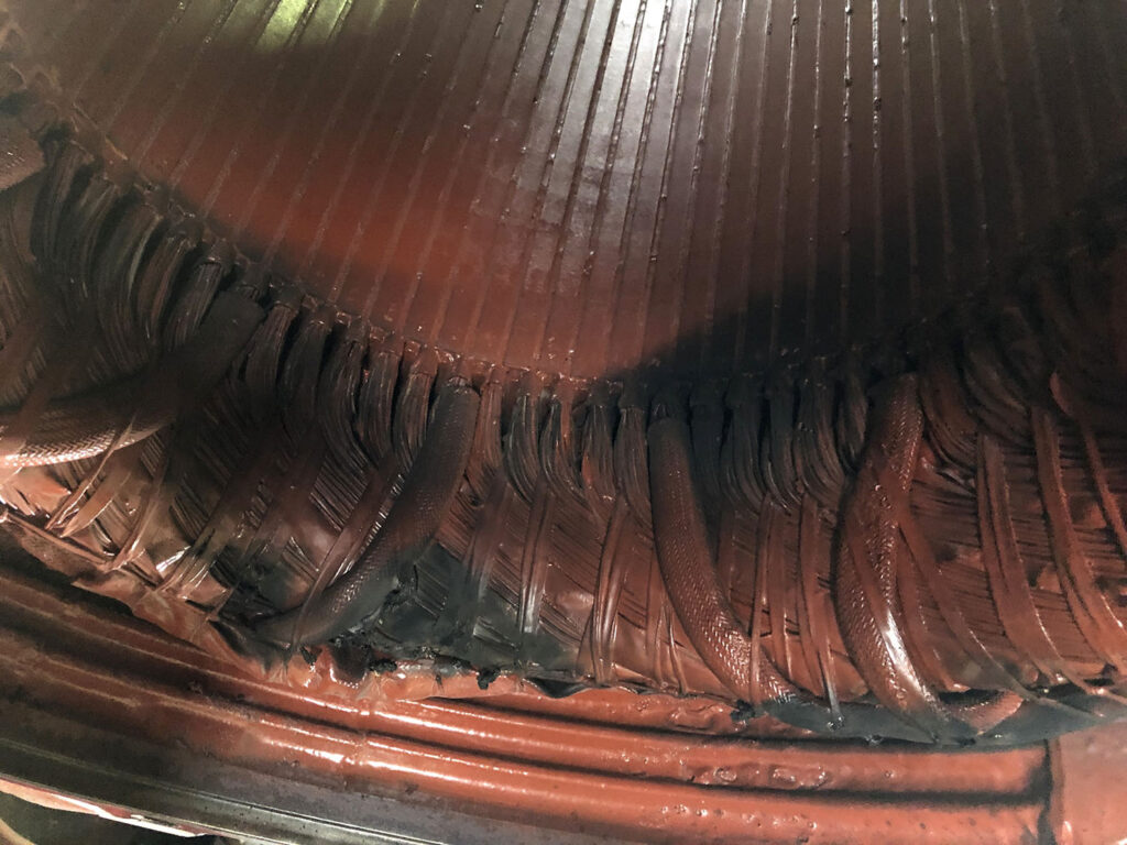
VFDs control motors with a simulated AC sine wave known as Pulse Width Modulation, or PWM. The problem is that peak voltages created by the VFD can often get high enough to break through motor insulation and short out motor windings.
The first thing you can do to protect yourself against this type of failure is to use “VFD-rated” motors, also called “inverter duty” motors. Over time I’ve seen this term broadly misused so as a quick summary: NEMA MG1 part 31 is the specification for VFD-rated motors and specifies the use of premium VFD insulation. This specification is what makes a motor VFD-rated as defined by NEMA. Be sure to include this on your checklist or spec when purchasing new motors.
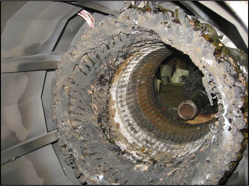
(2) VFDs Destroy Motor Bearings
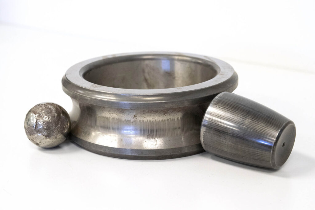
Even if you use a VFD-rated motor as defined by NEMA MG1 part 31, the motor is still unprotected from shaft currents created by VFDs. These shaft currents take functional and meticulously polished motor bearings and aggressively turn them into inoperative works of industrial art. This is a result of millions of little arcs per hour discharging through the motor bearings. These arcs destructively cause pitting, frosting, and fluting in motor bearings and bearing races, resulting in premature motor failure.
There is no magic bullet to send these shaft currents to the afterlife. However, you can redirect and neutralize their harmful effects on the motor and motor bearings a few different ways. This can be accomplished through a combination of technologies, such as shaft grounding rings, grounding straps, ceramic bearings, insulated motor housings, and even coated bearing races. The best solution or combination of solutions will vary based on your specific application.
(3) VFDs Burn Up Motors Because They Can’t Cool Themselves
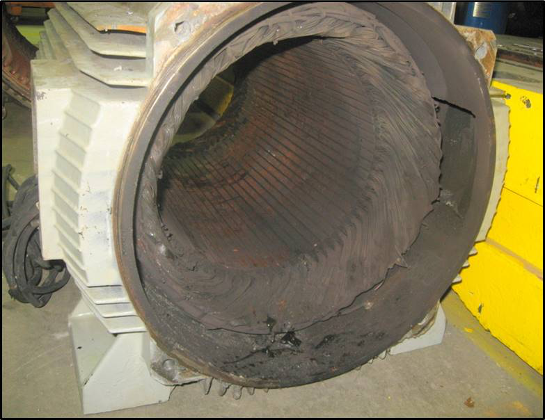
Generally, when a VFD is used on a motor, it’s because you aren’t going to run it at full speed (at least not all the time). As you slow the motor down it gets less cooling because the motor’s internal cooling fan isn’t rotating at full speed. It’s important to note that this isn’t only the case for extremely low speeds, say below 20Hz. Anything under the full rated motor speed reduces the cooling fan’s effectiveness and results in increased heat, lessening the motor’s operating life.
Unless you are continually running at extremely slow speeds, correcting this problem is fairly simple. Make sure that when you purchase a new motor it is nameplated with a service factor of 1.15 or more. Some of you may be thinking, “when a motor is operated from a VFD the service factor goes away”, and you’d be right. However, the increased service factor will give you that extra thermal margin to allow the motor to run cool and have a normal life expectancy.
If you are running at lower speeds or find yourself needing additional cooling, a constant speed blower is a wise addition. This will provide maximum cooling no matter the speed of the motor.
(4) VFDs (with Long Motor Lead Lengths) Harm Motor Windings
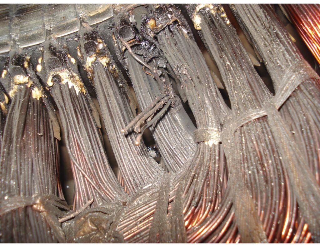
On long motor lead applications, the VFD PWM pulses build on each other, creating peak voltages that quickly break down motor insulation and short motor windings. Rules of thumb vary, but I suggest that you take a hard look at applications that have cable runs over 100 feet (30 meters). I recommend this because when you evaluate the cost of downtime on critical applications or the cost to push and pull submersible pump motors, it makes taking unnecessary risks seem irrational.
I recently spoke to an electrical superintendent that lost 8 inverter-duty rated 500HP Baldor motors in less than 3 months because of this issue. I mention the Baldor name because I believe they make high quality motors and suggest that not only would any motor have failed in this situation, but some would have likely failed sooner as the peak voltages exceeded 1500V. For reference, lead lengths in this particular situation were less than 400 feet from VFD to motor.
There are three solutions that are commonly considered when addressing this problem. The first is the simplest, which is to select a VFD that will automatically adjust the switching of its transistors and limit voltage spikes on long lead applications. This technology is sometimes referred to as “Soft PWM” and has performed favorably in many applications. A NEMA MG1 part 31 motor should still be used.
Second is to install a dV/dt filter on the output of your VFD, which will typically limit peak voltage spikes to about 975V on a 480V system. Generally, if your motor meets the NEMA MG1 part 30 or part 31 standards, a dV/dt filter works really well for most situations.
The third is the premium option, which is the use of sine wave filters on the output of the VFD. A sine wave filter converts the PWM wave from a VFD into a clean sine wave and will keep voltage peaks at or below ~800V on 480V systems. In my experience, sine wave filters work extraordinarily well, but often cost as much or more than a VFD chassis, making them a less attractive purchasing option. However, as mentioned above, that cost may be irrelevant when compared to the expense of downtime or push and pull costs.
Got More Motor Questions? We Can Help!
Call 800-595-5315 Or Connect With Our Expert Technicians Here:
Other Articles
- Critical Spare Planning

- The Three Most Common Externally Caused Motor Failures
- Remedies For Common Motor Winding Failures


Vice President of Sales
Motor & VFD guru, VFD applications expert, medium voltage VFD expert, leading E-commerce sales at Energy Management Corp, 10 Years in the Electrical Automation Industry


Great information, seems like a decent trade off to get speed control using VFDs.
Super helpful article with very valid points!
Some genuinely helpful articles on this site, saved to my bookmarks.
Very good article. I definitely love this website. Keep it up!
Very nice information.. I need to make sure to follow these best practices.