Motor shop’s process of inspection, machining, and rewinding
In this second article in our four article series highlighting our motor shop, we will be discussing the mechanical inspection, machining, and rewinding processes that are followed here at Energy Management Corporation to ensure the best results for your motor repair.
Mechanical Inspection
Once all parts are cleaned, they are visually inspected for any broken bolts, cracks, or any other visible damage. All damage is photographed and noted in the customer’s sales order for easy reference later on.
The rotor is then installed onto parallel rollers. Runout measurements are taken on the shaft and the rotor iron and are then documented. Once the rotor runout is checked, mechanical measurements are taken at six different points on all critical areas of the shaft, which includes both the journals and the coupling fit. These measurements are then compared to the allowable acceptable limits within EASA AR-100 and deemed pass or fail. Photos are then taken of any damage and added to the sales order.
The bearing housing is then mechanically inspected using the aforementioned six point measurement practice. The measurements are documented and compared against AR-100 standards and photos are taken of any damage and recorded for reference.
Machining of Housings and Rotors/Shafts (Only if Applicable)
Housings: If the housing has failed the allowable tolerance of the mechanical inspection, it is usually repaired by machining out the old material and installing a new sleeve. This process begins with the housing being dialed up using a dial indicator. Here, we will average out the Total Indicator Reading or tapering. The housing is then set up on the lathe and cuts are taken to remove only enough material to leave the new sleeve with an interference fit. Once that process is completed, the sleeve is shrunk in liquid nitrogen for a few moments and then slid into position on the housing once it reaches the proper size. We then use an industrial retaining compound to lock the sleeve into place. Once the sleeve reaches the ambient temperature of the housing, it can be machined to the proper dimensions. After the final dimensions are machined into the sleeve, they are recorded into our system and signed off on by the machinist.
Rotor/Shaft: When a shaft dimension is found to be out of tolerance, it is typically welded and machined back to an allowable tolerance. This includes setting up the shaft on a lathe and undercutting it by approximately .050 inches to allow the final dimension to be cut in the center of the soon-to-be-applied weld. The rotor is then moved to a welding lathe where it will be preheated before the final welding process. Once it reaches the appropriate temperature, the shaft is MIG welded to place a build that will be machined off to the proper tolerance. After welding, the shaft is heated again to the desired temperature. Once the welded part is post-heated it is covered, usually overnight, to allow a slow normalizing back to ambient temperature. This keeps the steel from crystalizing and creating stress fractures that could lead to a catastrophic failure when the motor is back to its intended use. Once the shaft reaches ambient temperature, it is moved back to the lathe to dial in the measurements and start the machining process. After the machining process is complete and the tolerances are within that of the ANSI/EASA AR-100, the dimensions are recorded for reference, and the rotor is prepped for paint and balancing.
Rewinding (Only if Applicable)
Prior to rewind, incoming stator core measurements are taken, the data is entered into our core-loss software, and the measurements are converted into core steel weight. Then, a core test is performed and pre-burn data is recorded. For random wound motors, opposite connection end turns are cut. A hole is then drilled into the copper to add a burn oven Resistance Temperature Detector (RTD) for monitoring. The stator is installed in our temperature-controlled burn oven for a period of 14+ hours, depending on its physical size. During this process, the temperature is recorded and constantly monitored electronically to be sure the temperature does not exceed 700 degrees Fahrenheit at any point in the burn cycle.
Once the burn cycle is complete, the stator is normalized to room temperature before it is removed from the oven to ensure it does not warp or crack. Once the stator has reached ambient temperature it is removed from the oven and winding data is taken from the unit and verified (or redesigned) through the EASA verification 4.0 database.
The winding is then carefully removed as to not splay the iron teeth. After winding removal, the core is blasted using crushed walnut shell. This ensures the laminations are not rolled over and allowed to short against each other. After the stator is cleaned a post core test is performed.
The core must have only changed by less than 20% and the watts/lb. should be a maximum of 4 to qualify for EASA accreditation and the Green Motors incentive program for maintaining motor efficiency. Once the stator passes the post core test and a hot spot check, it is prepped for the installation of our Class H insulation system.
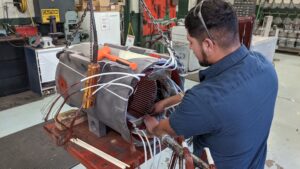
On a random wound machine, the circular mills per amp are calculated based upon design and slot fill. The wire in hand is then removed and our automated coil machine is set up for the correct dimensions to make the new coils. One test coil is made and measured, and adjustments are made, if needed, before all coils are completed. The coils are then made and stacked on a coil tree to prepare for installation. Then, one of our qualified technicians will install the carefully measured coils and brand new insulation.
Once the coils are installed, the winding connection is laid out and double checked. The leads and connections are welded and insulated, the coil end turns are shaped and tied, and the housings are checked to ensure proper fit and make sure that they will clear the new winding.
The stator is then pre-heated to 325 degrees Fahrenheit for four hours to remove any moisture and wax/oil from the wire that is used during the wire manufacturing process. After the pre-heat is completed, the stator is then cooled to 150 degrees Fahrenheit and lowered into our Vacuum Pressure Impregnation (VPI) system.
The stator then goes through the VPI process where the polyester resin, CC-1305, will be introduced to the green winding and fill any air voids within the winding. It is then re-baked for a minimum of eight hours at 325 degrees Fahrenheit. Depending on the size and voltage of the stator, it can go through as many as 3 VPI cycles to ensure proper impregnation.
After the final VPI and bake process is complete, and the stator has cooled to ambient temperature, the final electrical tests are performed. All components are tested to ANSI/EASA AR100-2015 standards. After testing is completed, excess varnish is removed and the mounting points are drilled and tapped. The bore is then ground and the stator is ready for the assembly process.
Got More Motor Questions? We Can Help!
Call 800-595-5315 Or Connect With Our Expert Technicians Here:
Other Articles
- Critical Spare Planning

- The Three Most Common Externally Caused Motor Failures
- Remedies For Common Motor Winding Failures

Director of Motor Service
Josh has over 20 years of experience in electric motor repair, as well as welding and machining. He is also an expert mechanic. He is in charge of our motor service centers in all 5 EMC locations.